Previous PageNext Page

TIMERS

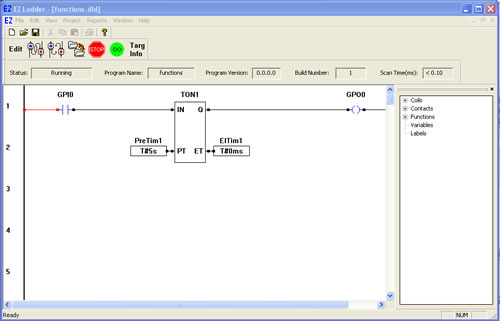
TON - On Delay Timer
The TON function is an On Delay timer with a programmable turn on time. When the input (IN) input is true, the timer begins timing. When the elapsed time (ET) is equal to the preset time (PT), the output (Q) energizes (goes true). When the input (IN) sees a true to false transition, the timer is reset and the output (Q) is de-energized (goes false).
  1. We will now use the TON in a ladder diagram.
  2. Place EZ LADDER® in the Edit mode (if in the Monitor mode).
  3. Close any currently open ladder diagrams (save them if necessary).
  4. Create a NEW ladder diagram Project.
  5. Configure the target as follows: (if you use a different target, some of the features may not be available)
    1. PLC on a Chip, Model PLCHIP-M2-25631
    2. Install Digital Inputs : GPI0 - GPI7
    3. Install Digital Outputs : GPO0 - GPO7
    4. Install Analog Block Analog Block 0
    5. Install the Real Time Clock
    6. Install the SSI Bus
  6. Using the Insert Function drop down menu on the tool bar, select TON or use the TON button on the tool bar.
  7. Place the cursor on Rung 1 near the center of the ladder diagram workspace and left-click to place the object. The Function Block properties dialog box will appear. Keep the name TON1 and leave the description blank (The name field allows you to set any name for the function while the description allows you to set a text description of what the function is used for). Click OK. The TON1 is now placed on rung 1.
  8. Select the DIRECT CONTACT button from the tool bar.
  9. Place the cursor on Rung 1 near the left power rail and left-click to place the contact. The Contact properties dialog box will appear. Using the drop down menu in the dialog box, selct GPI0 and click OK. This finishes the placement of the contact that is tied directly to hardware input GPI0 (also named GPI0).
  10. Select the DIRECT COIL button from the tool bar.
  11. Place the cursor on Rung 1 near the right power rail and left-click to place the coil. The Coil properties dialog box will appear. Using the drop down menu in the dialog box, selct GPO0 and click OK. This finishes the placement of the contact that is tied directly to hardware output GPO0 (also named GPO0).
  12. Select the HORIZONTAL LINK tool.
  13. Draw a link from the right side of the GPI0 contact to the IN of TON1.
  14. Draw a link from the Q output of TON1 to the left side of the GPO0 coil.
  15. We now need to insert variables to give the TON1 timer setpoints. Select the INST VARS button from the tool bar.
  16. Place the cursor on Rung 2 just left of the PT (preset time) input on TON1. Left-click to insert the variable. The Variables dialog box will appear (the only tab available will be the TIMER tab) since this is connecting to a timer.
  17. Click the ADD button to add a new timer variable. The Add timer dialog box will appear. Type PreTim1 for the Name and enter 5 for the seconds then click OK. This sets the variable connected to the timer's preset time to 5 seconds.
  18. With the INST VARS button still selected, place the cursor on Rung 2 just right of the ET (elapsed time) output on TON1. Left-click to insert the variable. The Variables dialog box will appear (the only tab available will be the TIMER tab) since this is connecting to a timer.
  19. Click the ADD button to add a new timer variable. The Add timer dialog box will appear. Type ElTim1 for the Name and leave the time blocks empty.Click OK. This sets the variable connected to the timers elapsed time to this variable (which can be used to view the current timer value when running the program on the target).
  20. Save the ladder diagram from the File menu and selecting SAVE. It is a good idea to periodically save your ladder diagram when developing it.
  21. Compile the target using the COMPILE button from the tool bar. Ensure that the compile is successful and there are no errors. If there are errors they must be corrected. Your ladder diagram should look similar to this:


  22. We are now ready to run the program on the target. Switch to the Monitor mode by clicking the MON button from the tool bar.
  23. Connect to the target, by selecting the CONNECT button from the tool bar. If a different program is running, just click OK.
  24. Download the ladder diagram to the target by selecting the DOWNLOAD button from the tool bar. If successful, the ladder diagram is now operating on the target. It should look similar to:


  25. Close the switch that is connected to Input 0 on the Development Board. GPI0 turns red indicating power flow and the timer begins timing. When the elapsed Timer reaches the preset time of 5 seconds, the output GPO0 turns red indicating it has power flow (and Output 0 on the Development Board is on).
  26. Open the switch to Input 0 and the GPI0 turns blue showing no power flow, the timer is reset and the GPO0 output turns blue showing no power flow.

You have completed the TON exercise.

  Previous PageNext Page