Previous PageNext Page

TIMERS

TOF - Off Delay Timer
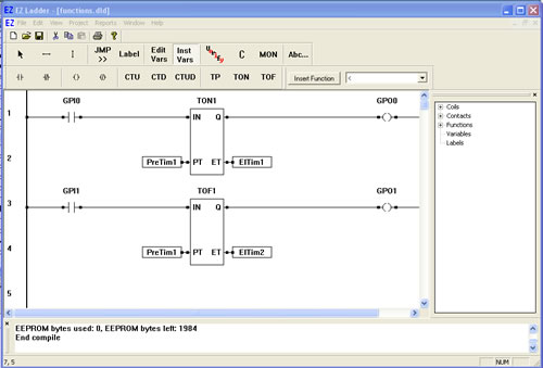
The TOF function is an Off Delay timer with a programmable turn off time. When the input (IN) input is true, the output (Q) is true. When the input (IN) sees a transition from true to false, the timer begins timing. When the elapsed time (ET) is equal to the preset time (PT), the output (Q) de-energizes (goes false). When the input (IN) sees a false to true to false transition, the timer is reset and begins timing again.
  1. We will now add the TOF to our previously created ladder diagram.
  2. Place EZ LADDER® in the Edit mode (if in the Monitor mode).
  3. Using the Insert Function drop down menu on the tool bar, select TOF or use the TOF button on the tool bar.
  4. Place the cursor on Rung 3 near the center of the ladder diagram workspace and left-click to place the object. The Function Block properties dialog box will appear. Keep the name TOF1 and leave the description blank (The name field allows you to set any name for the function while the description allows you to set a text description of what the function is used for). Click OK. The TOF1 is now placed on rung 3.
  5. Select the DIRECT CONTACT button from the tool bar.
  6. Place the cursor on Rung 3 near the left power rail and left-click to place the contact. The Contact properties dialog box will appear. Using the drop down menu in the dialog box, selct GPI1 and click OK. This finishes the placement of the contact that is tied directly to hardware input GPI1 (also named GPI1).
  7. Select the DIRECT COIL button from the tool bar.
  8. Place the cursor on Rung 3 near the right power rail and left-click to place the coil. The Coil properties dialog box will appear. Using the drop down menu in the dialog box, selct GPO1 and click OK. This finishes the placement of the contact that is tied directly to hardware output GPO1 (also named GPO1).
  9. Select the HORIZONTAL LINK tool.
  10. Draw a link from the right side of the GPI1 contact to the IN of TOF1.
  11. Draw a link from the Q output of TOF1 to the left side of the GPO1 coil.
  12. We now need to insert variables to give the TOF1 timer setpoints. Select the INST VARS button from the tool bar.
  13. Place the cursor on Rung 4 just left of the PT (preset time) input on TOF1. Left-click to insert the variable. The Variables dialog box will appear (the only tab available will be the TIMER tab) since this is connecting to a timer.
  14. Select the already existing variable named PreTim1 from the list and then click OK. This sets the variable connected to the timer's preset time to 5 seconds.
  15. With the INST VARS button still selected, place the cursor on Rung 4 just right of the ET (elapsed time) output on TOF1. Left-click to insert the variable. The Variables dialog box will appear (the only tab available will be the TIMER tab) since this is connecting to a timer.
  16. Click the ADD button to add a new timer variable. The Add timer dialog box will appear. Type ElTim2 for the Name and leave the time blocks empty.Click OK. This sets the variable connected to the timers elapsed time to this variable (which can be used to view the current timer value when running the program on the target).
  17. Save the ladder diagram from the File menu and selecting SAVE. It is a good idea to periodically save your ladder diagram when developing it.
  18. Compile the target using the COMPILE button from the tool bar. Ensure that the compile is successful and there are no errors. If there are errors they must be corrected. Your ladder diagram should look similar to this:


  19. We are now ready to run the program on the target. Switch to the Monitor mode by clicking the MON button from the tool bar.
  20. Connect to the target, by selecting the CONNECT button from the tool bar. A dialog box will appear stating the "builds" of the programs are different (because you have recompiled the program again). Click OK to continue.
  21. Download the ladder diagram to the target by selecting the DOWNLOAD button from the tool bar. If successful, the ladder diagram is now operating on the target. It should look similar to:


  22. Close the switch that is connected to Input 1 on the Development Board. GPI1 turns red indicating power flow and GPO1 turns red indicating power flow.
  23. Open the switch that is connected to Input 1 on the Development Board and the timer begins timing. When the elapsed Timer reaches the preset time of 5 seconds, the output GPO1 turns blue indicating no power flow (and Output 1 on the Development Board is off).

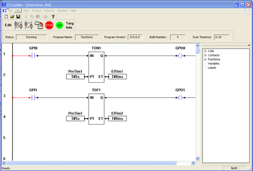
You have completed the TOF exercise.

Note: The TON timer circuit is still functional in addtion to the TOF timer circuit you just created.

  Previous PageNext Page