Previous PageNext Page

TIME / DATE

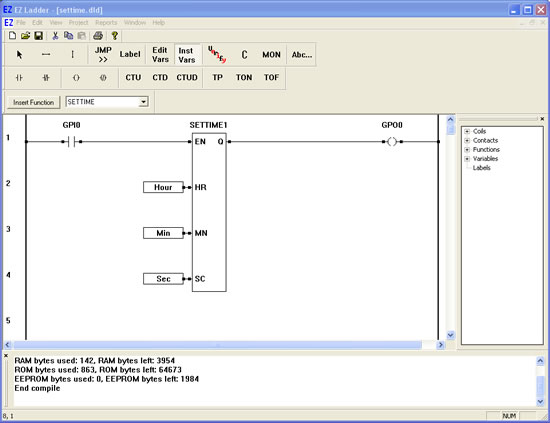
SETTIME- Sets the Real Time Clock Time

The SETTIME function sets the current time on the hardware real time clock. The time is set by using variables to apply values to each of the inputs. The enable (EN) must be true for the SETTIME function to be enabled.

  1. We will now use the SETTIME function in a ladder diagram.
  2. Place EZ LADDER® in the Edit mode (if in the Monitor mode).
  3. Close any currently open ladder diagrams (save them if necessary).
  4. Create a NEW ladder diagram Project.
  5. Configure the target as follows: (if you use a different target, some of the features may not be available)
    1. PLC on a Chip, Model PLCHIP-M2-25631
    2. Install Digital Inputs : GPI0 - GPI7
    3. Install Digital Outputs : GPO0 - GPO7
    4. Install Analog Block Analog Block 0
    5. Install the Real Time Clock
    6. Install the SSI Bus
  6. Using the Insert Function drop down menu on the tool bar, select SETTIME.
  7. Place the cursor on Rung 1 near the center of the ladder diagram workspace and left-click to place the object. The SETTIME is now placed.
  8. Select the DIRECT CONTACT button from the tool bar.
  9. Place the cursor on Rung 1 near the left power rail and left-click to place the contact. The Contact properties dialog box will appear. Using the drop down menu in the dialog box, selct GPI0 and click OK. This finishes the placement of the contact that is tied directly to hardware input GPI0 (also named GPI0).
  10. Select the DIRECT COIL button from the tool bar.
  11. Place the cursor on Rung 1 near the right power rail and left-click to place the contact. The Coil properties dialog box will appear. Using the drop down menu in the dialog box, selct GPO0 and click OK. This finishes the placement of the coil that is tied directly to hardware input GPO0 (also named GPO0).
  12. Select the HORIZONTAL LINK tool.
  13. Draw a link from the right side of the GPI0 contact to the EN input on the SETTIME function.
  14. Draw a link from the Q output of SETTIME to the left side of the GPO0 coil.
  15. We now need to insert variables to give the SETTIME its parameters and output. Select the INST VARS button from the tool bar.
  16. Place the cursor on Rung 2 just left of the HR input on SETTIME. Left-click to insert the variable. The Variables dialog box will appear (the only tab available will be the INTEGER tab) since this is connecting to the SETTIME.
  17. Click the ADD button to add a new variable. The Add variable dialog box will appear. Type Hour for the Name, select INTERNAL as the variable type and set the DEFAULT VALUE to what hour it is (0-23), then click OK. This is the the current hour.
  18. With the INST VARS still selected, place the cursor on Rung 3 just left of the MN input on SETTIME. Left-click to insert the variable. The Variables dialog box will appear (the only tab available will be the INTEGER tab) since this is connecting to an SETTIME.
  19. Click the ADD button to add a new variable. The Add variable dialog box will appear. Type Min for the Name, select INTERNAL as the variable type and set the DEFAULT VALUE to what minute it is (0-59), then click OK. This is the current minute.
  20. With the INST VARS still selected, place the cursor on Rung 4 just left of the SC input on SETTIME. Left-click to insert the variable. The Variables dialog box will appear (the only tab available will be the INTEGER tab) since this is connecting to an SETTIME.
  21. Click the ADD button to add a new variable. The Add variable dialog box will appear. Type Sec for the Name, select INTERNAL as the variable type and set the DEFAULT VALUE to what second it is (0-59), then click OK. This is the current seconds.
  22. Save the ladder diagram from the File menu and selecting SAVE. It is a good idea to periodically save your ladder diagram when developing it.
  23. Compile the target using the COMPILE button from the tool bar. Ensure that the compile is successful and there are no errors. If there are errors they must be corrected. Your ladder diagram should look similar to this:


  24. We are now ready to run the program on the target. Switch to the Monitor mode by clicking the MON button from the tool bar.
  25. Connect to the target, by selecting the CONNECT button from the tool bar. If a different program is running, just click OK.
  26. Download the ladder diagram to the target by selecting the DOWNLOAD button from the tool bar. If successful, the ladder diagram is now operating on the target. It should look similar to:


  27. Close the switch connected to Input 0. GPI0 is true causing power flow. This will cause the SETTIME function to be enabled.
  28. The time is now set provided that the hardware target supports the real time clock.
  29. Open the switch connected to input 0 (GPI0). The time will still be set as the time need only be set once as it is maintained in the real time clock and is battery protected from power loss.

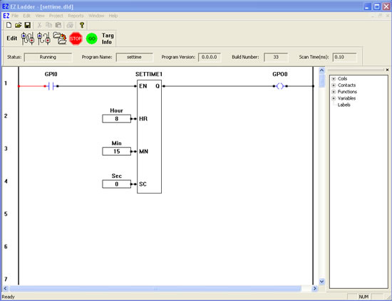
You have completed the SETTIME exercise.

  Previous PageNext Page