Previous PageNext Page

BISTABLES

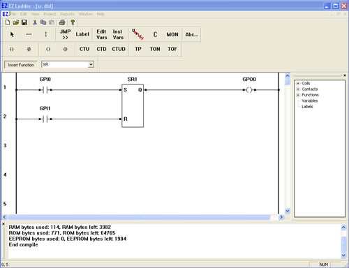
SR- Set Dominant Bistable

The SR function acts as a set dominant bistable. If the set input (S) is true, the output (Q) is true. A true on the reset (R) input sets the output (Q) to false only if the set (S) input is also false.

  1. We will now use the SR function in a ladder diagram.
  2. Place EZ LADDER® in the Edit mode (if in the Monitor mode).
  3. Close any currently open ladder diagrams (save them if necessary).
  4. Create a NEW ladder diagram Project.
  5. Configure the target as follows: (if you use a different target, some of the features may not be available)
    1. PLC on a Chip, Model PLCHIP-M2-25631
    2. Install Digital Inputs : GPI0 - GPI7
    3. Install Digital Outputs : GPO0 - GPO7
    4. Install Analog Block Analog Block 0
    5. Install the Real Time Clock
    6. Install the SSI Bus
  6. Using the Insert Function drop down menu on the tool bar, select SR.
  7. Place the cursor on Rung 1 near the center of the ladder diagram workspace and left-click to place the object. Leave the name SR1 and click OK. The SR is now placed.
  8. Select the DIRECT CONTACT button from the tool bar.
  9. Place the cursor on Rung 1 near the left power rail and left-click to place the contact. The Contact properties dialog box will appear. Using the drop down menu in the dialog box, selct GPI0 and click OK. This finishes the placement of the contact that is tied directly to hardware input GPI0 (also named GPI0).
  10. With the DIRECT CONTACT still selected, place the cursor on Rung 2 near the left power rail and left-click to place the contact. The Contact properties dialog box will appear. Using the drop down menu in the dialog box, selct GPI1 and click OK. This finishes the placement of the contact that is tied directly to hardware input GPI1 (also named GPI1).
  11. Select the DIRECT COIL button from the tool bar.
  12. Place the cursor on Rung 1 near the right power rail and left-click to place the contact. The Coil properties dialog box will appear. Using the drop down menu in the dialog box, selct GPO0 and click OK. This finishes the placement of the coil that is tied directly to hardware input GPO0 (also named GPO0).
  13. Select the HORIZONTAL LINK tool.
  14. Draw a link from the right side of the GPI0 contact to the S input on the SR function.
  15. Draw a link from the right side of the GPI1 contact to the R input on the SR function.
  16. Draw a link from the Q output of SR to the left side of the GPO0 coil.
  17. Save the ladder diagram from the File menu and selecting SAVE. It is a good idea to periodically save your ladder diagram when developing it.
  18. Compile the target using the COMPILE button from the tool bar. Ensure that the compile is successful and there are no errors. If there are errors they must be corrected. Your ladder diagram should look similar to this:


  19. We are now ready to run the program on the target. Switch to the Monitor mode by clicking the MON button from the tool bar.
  20. Connect to the target, by selecting the CONNECT button from the tool bar. If a different program is running, just click OK.
  21. Download the ladder diagram to the target by selecting the DOWNLOAD button from the tool bar. If successful, the ladder diagram is now operating on the target. It should look similar to:


  22. Momentarily close the switch connected to Input 0. GPI0 is momentarily true causing power flow. The GPO0 output will now be latched true (showing power flow).
  23. Momentarily close the switch connected to Input 1. GPI1 is momentarily true causing power flow. The GPO0 output will now be false (showing no power flow).
  24. Close the switch connected to Input 0. GPI0 is momentarily true causing power flow. The GPO0 output will now be latched true (showing power flow).
  25. Close the switch connected to Input 1. GPI1 is momentarily true causing power flow. The GPO0 output remains true (showing power flow).
  26. Open the switchs connected to Input 0 and Input 1.

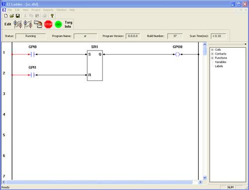
You have completed the SR exercise.

  Previous PageNext Page