Previous PageNext Page

DRUM SEQUENCERS

Drum Sequencer
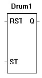
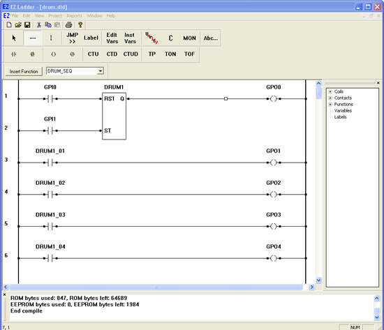
The DRUM_SEQ function steps through a pre-programmed set of on/off channel (contact) settings when the ST input is pulsed. The drum sequence is programmed with a maximum of 32 channels. Each channel may be programmed to be on or off (1 or 0) for each step. When the ST input is pulsed, the drum sequencer increments to the next step and the channel’s contacts change to the appropriate state.

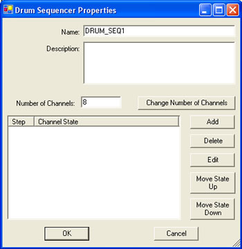
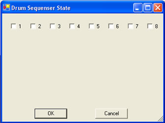
Each channel is designed to represent a contact. When the channel is set to 0 (off), its contact is false. When the channel is set to 1 (on), its contact is true. The contacts are automatically named according to the DRUM_SEQ name. The channel settings are defined in a matrix. For each step in the drum sequencer, using the check box, select the state of each channel for each drum sequencer step.

  1. We will now use the Drum Sequencer in a ladder diagram.
  2. Place EZ LADDER® in the Edit mode (if in the Monitor mode).
  3. Close any currently open ladder diagrams (save them if necessary).
  4. Create a NEW ladder diagram Project.
  5. Configure the target as follows: (if you use a different target, some of the features may not be available)
    1. PLC on a Chip, Model PLCHIP-M2-25631
    2. Install Digital Inputs : GPI0 - GPI7
    3. Install Digital Outputs : GPO0 - GPO7
    4. Install Analog Block Analog Block 0
    5. Install the Real Time Clock
    6. Install the SSI Bus
  6. Using the Insert Function drop down menu on the tool bar, select DRUM_SEQ..
  7. Place the cursor on Rung 1 near the center of the ladder diagram workspace and left-click to place the object. The Drum Sequencer Properties dialog box will appear.
  8. Change the name to DRUM1 and leave the description blank.
  9. Set the number of channels to 8. Do NOT click OK yet. You must set the drum steps up now.
  10. Click the ADD button. The Drum Sequencer State dialog box will appear.
  11. Place a check mark in box # 1. Click OK.
  12. Repeat steps 10 and steps 11. For each time, place a check mark in only the next numbered block (2-4 until there are a total of 4 steps).
  13. The drum sequencer properties should now look like this:
  14. Click OK to save the drum sequencer information and to complete the object placement.
  15. Select the DIRECT CONTACT button from the tool bar.
  16. Place the cursor on Rung 1 near the left power rail and left-click to place the contact. The Contact properties dialog box will appear. Using the drop down menu in the dialog box, selct GPI0 and click OK. This finishes the placement of the contact that is tied directly to hardware input GPI0 (also named GPI0).
  17. With the DIRECT CONTACT still selected, place the cursor on Rung 2 near the left power rail and left-click to place the contact. The Contact properties dialog box will appear. Using the drop down menu in the dialog box, selct GPI1 and click OK. This finishes the placement of the contact that is tied directly to hardware input GPI1 (also named GPI1).
  18. Select the DIRECT COIL button from the tool bar.
  19. Place the cursor on Rung 1 near the right power rail and left-click to place the coil. The Coil properties dialog box will appear. Using the drop down menu in the dialog box, selct GPO0 and click OK. This finishes the placement of the contact that is tied directly to hardware output GPO0 (also named GPO0).
  20. Select the HORIZONTAL LINK tool.
  21. Draw a link from the right side of the GPI0 contact to the RST of DRUM1.
  22. Draw a link from the right side of the GPI1 contact to the ST of DRUM1.
  23. Draw a link from the Q output of DRUM to the left side of the GPO0 coil.
  24. You must now draw rungs using the drum sequencer contacts.
  25. Select the DIRECT CONTACT button from the tool bar.
  26. Place the cursor on Rung 3 near the left power rail and left-click to place the contact. The Contact properties dialog box will appear. Using the drop down menu in the dialog box, selct DRUM1_01 and click OK. This is the channel 1 contact from DRUM1.
  27. With the DIRECT CONTACT still selected, place the cursor on Rung 4 near the left power rail and left-click to place the contact. The Contact properties dialog box will appear. Using the drop down menu in the dialog box, selct DRUM1_02 and click OK. This is the channel 2 contact from DRUM1.
  28. With the DIRECT CONTACT still selected, place the cursor on Rung 5 near the left power rail and left-click to place the contact. The Contact properties dialog box will appear. Using the drop down menu in the dialog box, selct DRUM1_03 and click OK. This is the channel 3 contact from DRUM1.
  29. With the DIRECT CONTACT still selected, place the cursor on Rung 6 near the left power rail and left-click to place the contact. The Contact properties dialog box will appear. Using the drop down menu in the dialog box, selct DRUM1_04 and click OK. This is the channel 4 contact from DRUM1.
  30. Select the DIRECT COIL button from the tool bar.
  31. Place the cursor on Rung 3 near the right power rail and left-click to place the coil. The Coil properties dialog box will appear. Using the drop down menu in the dialog box, selct GPO1 and click OK. This finishes the placement of the contact that is tied directly to hardware output GPO1 (also named GPO1).
  32. With the DIRECT COIL still selected, place the cursor on Rung 4 near the right power rail and left-click to place the coil. The Coil properties dialog box will appear. Using the drop down menu in the dialog box, selct GPO2 and click OK. This finishes the placement of the contact that is tied directly to hardware output GPO2 (also named GPO2).
  33. With the DIRECT COIL still selected, place the cursor on Rung 5 near the right power rail and left-click to place the coil. The Coil properties dialog box will appear. Using the drop down menu in the dialog box, selct GPO3 and click OK. This finishes the placement of the contact that is tied directly to hardware output GPO3 (also named GPO3).
  34. With the DIRECT COIL still selected, place the cursor on Rung 6 near the right power rail and left-click to place the coil. The Coil properties dialog box will appear. Using the drop down menu in the dialog box, selct GPO4 and click OK. This finishes the placement of the contact that is tied directly to hardware output GPO4 (also named GPO4).
  35. Select the HORIZONTAL LINK tool.
  36. Draw a link from the right side of the DRUM1_01 contact to the left side of the GPO1 coil.
  37. Draw a link from the right side of the DRUM1_02 contact to the left side of the GPO2 coil.
  38. Draw a link from the right side of the DRUM1_03 contact to the left side of the GPO3 coil.
  39. Draw a link from the right side of the DRUM1_04 contact to the left side of the GPO4 coil.
  40. Save the ladder diagram from the File menu and selecting SAVE. It is a good idea to periodically save your ladder diagram when developing it.
  41. Compile the target using the COMPILE button from the tool bar. Ensure that the compile is successful and there are no errors. If there are errors they must be corrected. Your ladder diagram should look similar to this:


  42. We are now ready to run the program on the target. Switch to the Monitor mode by clicking the MON button from the tool bar.
  43. Connect to the target, by selecting the CONNECT button from the tool bar. If a different program is running, just click OK.
  44. Download the ladder diagram to the target by selecting the DOWNLOAD button from the tool bar. If successful, the ladder diagram is now operating on the target. It should look similar to:


  45. Notice that GPO1 is true because DRUM1_01 is true (the first program step had channel 1 with a check box).
  46. Momentarily close the switch connected to Input 1 (ST drum input). GPI1 momentarily is true causing power flow. This will cause the drum sequencer to increment to the next "step". For each momentary close on the ST drum input, the drum sequencer will increment its step.
  47. Momentarily close the switch to Input 1 several times. Notice that for each instance of the switch closing, the outputs are cycling in order (as they were programmed in the drum sequencer properties. When the last step is reached, the drum sequencer automatically restarts from step 1.
  48. Momentarily close the switch connected to Input 0 (RST drum input). GPI0 momentarily is true causing power flow. This will cause the drum sequencer to reset to step 1.

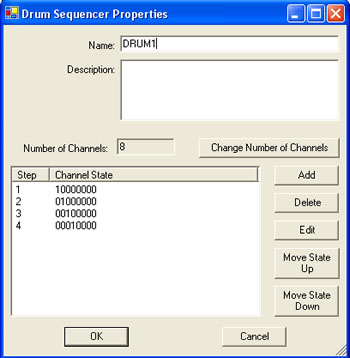
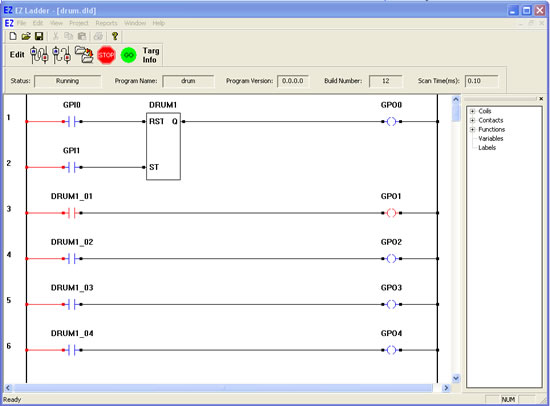
You have completed the Drum Sequencer exercise.

  Previous PageNext Page