Previous PageNext Page

COUNTERS

CNTRTMR - Hardware Counter / Timer
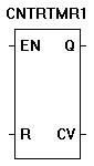
The CNTRTMR function provides access and functionality to a hardware timer or counter (must be supported by target).

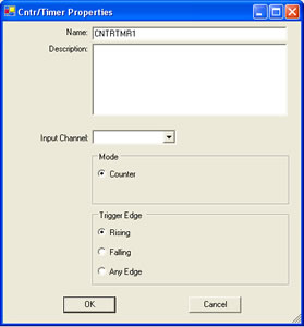
When configured as a counter, the the trigger can be set to rising or falling edge of the input pulse on the EN input. R resets the current counter value (CV). Q is true when the counter is counting.

When configured as a timer, the trigger may bes set to rising, falling or any edge of the input pulse on the EN input. R resets the current timer value (CV). Q is true when the timer is counting. The timer resolution is .042 microseconds.

  1. We will now use the CNTRTMR in a ladder diagram.
  2. Place EZ LADDER® in the Edit mode (if in the Monitor mode).
  3. Close any currently open ladder diagrams (save them if necessary).
  4. Create a NEW ladder diagram Project.
  5. Configure the target as follows: (if you use a different target, some of the features may not be available)
    1. PLC on a Chip, Model PLCHIP-M2-25631
    2. Install Digital Inputs : GPI0 - GPI7
    3. Install Digital Outputs : GPO0 - GPO7
    4. Install Analog Block Analog Block 0
    5. Install the Real Time Clock
    6. Install the SSI Bus
  6. Using the Insert Function drop down menu on the tool bar, select CNTRTMR..
  7. Place the cursor on Rung 1 near the center of the ladder diagram workspace and left-click to place the object. The CNTR/TMR Properties dialog box will appear.
  8. Keep the name CNTRTMR1 and leave the description blank. Select Input Channel 1, Mode - Counter and Trigger Edge - Rising. Click OK. The CNTRTMR is now placed on rung 12.
  9. Select the DIRECT CONTACT button from the tool bar.
  10. Place the cursor on Rung 1 near the left power rail and left-click to place the contact. The Contact properties dialog box will appear. Using the drop down menu in the dialog box, selct GPI0 and click OK. This finishes the placement of the contact that is tied directly to hardware input GPI0 (also named GPI0).
  11. With the DIRECT CONTACT still selected, place the cursor on Rung 2 near the left power rail and left-click to place the contact. The Contact properties dialog box will appear. Using the drop down menu in the dialog box, selct GPI1 and click OK. This finishes the placement of the contact that is tied directly to hardware input GPI1 (also named GPI1).
  12. Select the DIRECT COIL button from the tool bar.
  13. Place the cursor on Rung 1 near the right power rail and left-click to place the coil. The Coil properties dialog box will appear. Using the drop down menu in the dialog box, selct GPO0 and click OK. This finishes the placement of the contact that is tied directly to hardware output GPO0 (also named GPO0).
  14. Select the HORIZONTAL LINK tool.
  15. Draw a link from the right side of the GPI0 contact to the EN of CNTRTMR1.
  16. Draw a link from the right side of the GPI1 contact to the R of CNTRTMR1.
  17. Draw a link from the Q output of CNTRTMR1 to the left side of the GPO0 coil.
  18. We now need to insert variables to give the CNTRTMR1 a place to store it's output. Select the INST VARS button from the tool bar.
  19. Place the cursor on Rung 2 just right of the CV (current value) output on CNTRTMR1. Left-click to insert the variable. The Variables dialog box will appear (the only tab available will be the INTEGER tab) since this is connecting to a counter.
  20. Click the ADD button to add a new variable. The Add variable dialog box will appear. Type CVal3 for the Name, select INTERNAL as the variable type an leave the DEFAULT VALUE blank, then click OK. This sets the variable connected to the counter's current value to this variable (which can be used to view the current counter value when running the program on the target).
  21. Save the ladder diagram from the File menu and selecting SAVE. It is a good idea to periodically save your ladder diagram when developing it.
  22. Compile the target using the COMPILE button from the tool bar. Ensure that the compile is successful and there are no errors. If there are errors they must be corrected. Your ladder diagram should look similar to this:


  23. We are now ready to run the program on the target. Switch to the Monitor mode by clicking the MON button from the tool bar.
  24. Connect to the target, by selecting the CONNECT button from the tool bar. If a different program is running, just click OK.
  25. Download the ladder diagram to the target by selecting the DOWNLOAD button from the tool bar. If successful, the ladder diagram is now operating on the target. It should look similar to:


  26. Close the switch connected to Input 0 (EN counter input). GPI0 is true causing power flow. This will cause the GPO0 output to be true.
  27. For each pulse on the actual hardware counter input (CT1 on the PLC on a Chip Development main board), the CVal will increment.
  28. Pulse the CT1 input several times and watch the count increase.
  29. Momentarily close the switch connected to Input 1 (R counter input). GPI1 momentarily is true causing power flow. This will cause the counter to reset, setting the CVal to zero.
  30. Open the switch connected to Input 0 (EN counter input). GPI0 is false indicating no power flow. This will cause the GPO0 output to be false.
  31. Pulse the CT1 input several times and notice the counter value does not increase when the EN input is false.

You have completed the CNTRTMR exercise.

  Previous PageNext Page