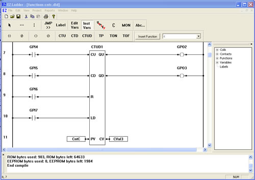
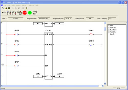
Previous PageNext Page

COUNTERS

CTUD- Up and Down Counter
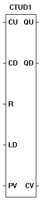
The CTUD function is programmable up/down counter. With reset (R) not active, a true on input (CU) will increment the current (CV) count by one, while a true on input (CD) will cause the current count (CV) to decrement by one. When the CV = PV, the output (QU) will be true. When the CV = 0, the output (QD) will be true. A true on the reset (R) will cause CV = 0, QU to go false and QD to go true. A true on the load (LD) will cause CV = PV, QU to go true and QD to go false. The reset (R) is dominant and takes priority over all inputs. The counter inputs trigger on a false to true transition on CU or CD.
  1. We will now use the CTUD in a ladder diagram.
  2. Place EZ LADDER® in the Edit mode (if in the Monitor mode).
  3. Using the Insert Function drop down menu on the tool bar, select CTUD or use the CTUD button on the tool bar.
  4. Place the cursor on Rung 7 near the center of the ladder diagram workspace and left-click to place the object. The Function Block properties dialog box will appear. Keep the name CTUD1 and leave the description blank (The name field allows you to set any name for the function while the description allows you to set a text description of what the function is used for). Click OK. The CTUD1 is now placed on rung 7.
  5. Select the DIRECT CONTACT button from the tool bar.
  6. Place the cursor on Rung 7 near the left power rail and left-click to place the contact. The Contact properties dialog box will appear. Using the drop down menu in the dialog box, selct GPI4 and click OK. This finishes the placement of the contact that is tied directly to hardware input GPI4 (also named GPI4).
  7. With the DIRECT CONTACT still selected, place the cursor on Rung 8 near the left power rail and left-click to place the contact. The Contact properties dialog box will appear. Using the drop down menu in the dialog box, selct GPI5 and click OK. This finishes the placement of the contact that is tied directly to hardware input GPI5 (also named GPI5).
  8. With the DIRECT CONTACT still selected, place the cursor on Rung 9 near the left power rail and left-click to place the contact. The Contact properties dialog box will appear. Using the drop down menu in the dialog box, selct GPI6 and click OK. This finishes the placement of the contact that is tied directly to hardware input GPI6 (also named GPI6).
  9. With the DIRECT CONTACT still selected, place the cursor on Rung 10 near the left power rail and left-click to place the contact. The Contact properties dialog box will appear. Using the drop down menu in the dialog box, selct GPI7 and click OK. This finishes the placement of the contact that is tied directly to hardware input GPI7 (also named GPI7).
  10. Select the DIRECT COIL button from the tool bar.
  11. Place the cursor on Rung 7 near the right power rail and left-click to place the coil. The Coil properties dialog box will appear. Using the drop down menu in the dialog box, selct GPO2 and click OK. This finishes the placement of the contact that is tied directly to hardware output GPO2 (also named GPO2).
  12. With the DIRECT COIL still selected, place the cursor on Rung 8 near the right power rail and left-click to place the coil. The Coil properties dialog box will appear. Using the drop down menu in the dialog box, selct GPO3 and click OK. This finishes the placement of the contact that is tied directly to hardware output GPO3 (also named GPO3).
  13. Select the HORIZONTAL LINK tool.
  14. Draw a link from the right side of the GPI4 contact to the CU of CTUD1.
  15. Draw a link from the right side of the GPI5 contact to the CD of CTUD1.
  16. Draw a link from the right side of the GPI6 contact to the R of CTUD1.
  17. Draw a link from the right side of the GPI7 contact to the LD of CTUD1.
  18. Draw a link from the QU output of CTUD1 to the left side of the GPO2 coil.
  19. Draw a link from the QD output of CTUD1 to the left side of the GPO3 coil.
  20. We now need to insert variables to give the CTUD1 setpoints. Select the INST VARS button from the tool bar.
  21. Place the cursor on Rung 11 just left of the PV (preset value) input on CTUD1. Left-click to insert the variable. The Variables dialog box will appear (the only tab available will be the INTEGER tab) since this is connecting to a counter.
  22. Click the ADD button to add a new variable. The Add variable dialog box will appear. Type CNTC for the Name, select INTERNAL as the variable type an enter 5 for the DEFAULT VALUE then click OK. This sets the variable connected to the counter's preset value to 5.
  23. With the INST VARS button still selected, place the cursor on Rung 11 just right of the CV (current value) output on CTUD1. Left-click to insert the variable. The Variables dialog box will appear (the only tab available will be the INTEGER tab) since this is connecting to a counter.
  24. Click the ADD button to add a new variable. The Add variable dialog box will appear. Type CVal3 for the Name, select INTERNAL as the variable type an leave the DEFAULT VALUE blank, then click OK. This sets the variable connected to the counter's current value to this variable (which can be used to view the current counter value when running the program on the target).
  25. Save the ladder diagram from the File menu and selecting SAVE. It is a good idea to periodically save your ladder diagram when developing it.
  26. Compile the target using the COMPILE button from the tool bar. Ensure that the compile is successful and there are no errors. If there are errors they must be corrected. Your ladder diagram should look similar to this:


  27. We are now ready to run the program on the target. Switch to the Monitor mode by clicking the MON button from the tool bar.
  28. Connect to the target, by selecting the CONNECT button from the tool bar. If a different program is running, just click OK.
  29. Download the ladder diagram to the target by selecting the DOWNLOAD button from the tool bar. If successful, the ladder diagram is now operating on the target. It should look similar to:


  30. Momentarily close the switch connected to Input 7 (LD counter input). GPI7 momentarily is true causing power flow. This will cause the counter to load the preset value (PV), making GPO3 false, GPO2 true and setting the CVal 3 to 5.
  31. Momentarily close the switch connected to Input 6 (R counter input). GPI6 momentarily is true causing power flow. This will cause the counter to reset, making GPO2 false, GPO3 true and setting the CVal 3 to zero.
  32. Momentarily close the switch connected to Input 4 (CU counter input). GPI4 momentarily is true causing power flow.This will cause the counter to increment the current count (CVal3). For each momentary close on the CU input, the counter will increment (counting up). Repeat this until there are 3 counts on CVal3.
  33. Momentarilly close the switch that is connected to Input 5 (CD coutner input). GPI5 momentarily turns red indicating power flow and the CVal3 variable is now decremented. For each momentary closure of the GPI5 input, the counter value decreases. When the counter value CVal3 is equal to zero, then GPO3 will turn red indicating power flow and the actual output will also be true.

You have completed the CTUD exercise.

  Previous PageNext Page