The LATCH coil acts like a direct coil, except once the coil is energized, it will maintain its energized state until the UNLATCH coil is triggered.
We will now use the LATCH coil in a ladder diagram.
Place EZ LADDER® in the Edit mode (if in the Monitor mode).
Close any currently open ladder diagrams (save them if necessary).
Create a NEW ladder diagram Project.
Configure the target as follows: (if you use a different target, some of the features may not be available)
PLC on a Chip, Model PLCHIP-M2-25631
Install Digital Inputs : GPI0 - GPI7
Install Digital Outputs : GPO0 - GPO7
Install Analog Block Analog Block 0
Install the Real Time Clock
Install the SSI Bus
Using the Insert Function drop down menu on the tool bar, select LATCH..
Place the cursor on Rung 1 near the right hand power rail and left-click to place the object. The Coil Properties dialog box will appear.
From the drop down box, select GPO0 and click OK to complete the object placement.
Select the DIRECT CONTACT button from the tool bar.
Place the cursor on Rung 1 near the left power rail and left-click to place the contact. The Contact properties dialog box will appear. Using the drop down menu in the dialog box, selct GPI0 and click OK. This finishes the placement of the contact that is tied directly to hardware input GPI0 (also named GPI0).
Select the HORIZONTAL LINK tool.
Draw a link from the right side of the GPI0 contact to the left side of the LATCH GPO0.
Save the ladder diagram from the File menu and selecting SAVE. It is a good idea to periodically save your ladder diagram when developing it.
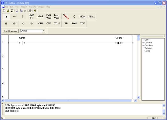
Compile the target using the COMPILE button from the tool bar. Ensure that the compile is successful and there are no errors. If there are errors they must be corrected. Your ladder diagram should look similar to this:
We are now ready to run the program on the target. Switch to the Monitor mode by clicking the MON button from the tool bar.
Connect to the target, by selecting the CONNECT button from the tool bar. If a different program is running, just click OK.
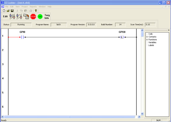
Download the ladder diagram to the target by selecting the DOWNLOAD button from the tool bar. If successful, the ladder diagram is now operating on the target. It should look similar to:
Notice that GPO0 is false because GPI0 is false.
Close the switch connected to Input 0. GPI0 is true causing power flow. This will cause the latch output GPO0 to be true.
Open the switch to Input 0. GPI0 is false indicating no power flow; however the latch output GPO0 remains true (because it is latched).
A LATCH output will maintain its state until it is released using an UNLATCH coil.