The UNLATCH coil acts like a direct coil, except when the coil is energized, it will cause its LATCHed coil counterpart to unlatch and de-energize.
We will now use the UNLATCH coil in a ladder diagram. We will build upon the previous LATCH coil example.
Place EZ LADDER® in the Edit mode (if in the Monitor mode).
Using the Insert Function drop down menu on the tool bar, select UNLATCH..
Place the cursor on Rung 2 near the right hand power rail and left-click to place the object. The Coil Properties dialog box will appear.
From the drop down box, select GPO0 and click OK to complete the object placement.
Select the DIRECT CONTACT button from the tool bar.
Place the cursor on Rung 2 near the left power rail and left-click to place the contact. The Contact properties dialog box will appear. Using the drop down menu in the dialog box, selct GPI1 and click OK. This finishes the placement of the contact that is tied directly to hardware input GPI1 (also named GPI1).
Select the HORIZONTAL LINK tool.
Draw a link from the right side of the GPI1 contact to the left side of UNLATCH GPO0.
Save the ladder diagram from the File menu and selecting SAVE. It is a good idea to periodically save your ladder diagram when developing it.
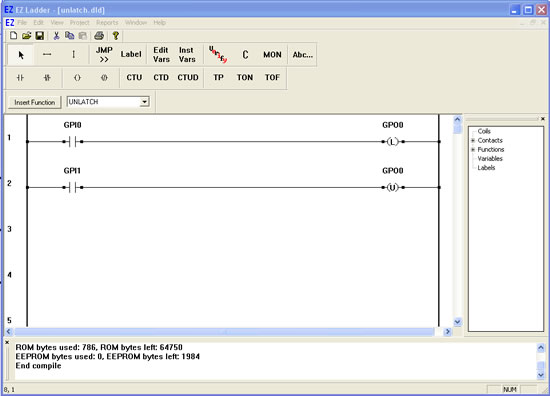
Compile the target using the COMPILE button from the tool bar. Ensure that the compile is successful and there are no errors. If there are errors they must be corrected. Your ladder diagram should look similar to this:
We are now ready to run the program on the target. Switch to the Monitor mode by clicking the MON button from the tool bar.
Connect to the target, by selecting the CONNECT button from the tool bar. If a different program is running, just click OK.
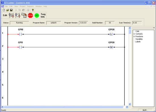
Download the ladder diagram to the target by selecting the DOWNLOAD button from the tool bar. If successful, the ladder diagram is now operating on the target. It should look similar to:
Notice that GPO0 is false because GPI0 is false.
Close the switch connected to Input 0. GPI0 is true causing power flow. This will cause the latch output GPO0 to be true.
Open the switch to Input 0. GPI0 is false indicating no power flow; however the latch output GPO0 remains true (because it is latched).
Close the switch connected to Input 1. GPI1 is true causing power flow. This will cause the latch output GPO0 to unlatch and be false..