Previous PageNext Page

BIT MANIPULATION

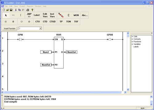
ROR - Rotate Bit Right

The ROR function provides a right-bit rotation of the P1 input. P2 specifies the number of one-bit rotations. The P1 number is a integer representation of a binary number. The P2 number is an integer representation of the number of binary rotations (shifts) to occur to P1. The actual bit only rotates when the minimum number is reached (example: 32 bit rotation to the input number 32). The enable (EN) must be true for the ROR function to be enabled. The Q output is true when the ROR function is enabled. The O Output is the rotated number (represented in integer form).

  1. We will now use the ROR function in a ladder diagram.
  2. Place EZ LADDER® in the Edit mode (if in the Monitor mode).
  3. Close any currently open ladder diagrams (save them if necessary).
  4. Create a NEW ladder diagram Project.
  5. Configure the target as follows: (if you use a different target, some of the features may not be available)
    1. PLC on a Chip, Model PLCHIP-M2-25631
    2. Install Digital Inputs : GPI0 - GPI7
    3. Install Digital Outputs : GPO0 - GPO7
    4. Install Analog Block Analog Block 0
    5. Install the Real Time Clock
    6. Install the SSI Bus
  6. Using the Insert Function drop down menu on the tool bar, select ROR.
  7. Place the cursor on Rung 1 near the center of the ladder diagram workspace and left-click to place the object. The ROR is now placed.
  8. Select the DIRECT CONTACT button from the tool bar.
  9. Place the cursor on Rung 1 near the left power rail and left-click to place the contact. The Contact properties dialog box will appear. Using the drop down menu in the dialog box, selct GPI0 and click OK. This finishes the placement of the contact that is tied directly to hardware input GPI0 (also named GPI0).
  10. Select the DIRECT COIL button from the tool bar.
  11. Place the cursor on Rung 1 near the right power rail and left-click to place the contact. The Coil properties dialog box will appear. Using the drop down menu in the dialog box, selct GPO0 and click OK. This finishes the placement of the coil that is tied directly to hardware input GPO0 (also named GPO0).
  12. Select the HORIZONTAL LINK tool.
  13. Draw a link from the right side of the GPI0 contact to the EN input on the ROR function.
  14. Draw a link from the Q output of ROR to the left side of the GPO0 coil.
  15. We now need to insert variables to give the ROR its parameters and output. Select the INST VARS button from the tool bar.
  16. Place the cursor on Rung 2 just left of the P1 input on ROR. Left-click to insert the variable. The Variables dialog box will appear (the only tab available will be the INTEGER tab) since this is connecting to the ROR.
  17. Click the ADD button to add a new variable. The Add variable dialog box will appear. Type Num1 for the Name, select INTERNAL as the variable type and set the DEFAULT VALUE to 32, then click OK. This is the number that will be rotated.
  18. With the INST VARS still selected, place the cursor on Rung 3 just left of the P2 input on ROR. Left-click to insert the variable. The Variables dialog box will appear (the only tab available will be the INTEGER tab) since this is connecting to an ROR.
  19. Click the ADD button to add a new variable. The Add variable dialog box will appear. Type NumRot for the Name, select INTERNAL as the variable type and set the DEFAULT VALUE to 0, then click OK. This is the number of rotations.
  20. With the INST VARS still selected, place the cursor on Rung 2 just right of the O output on ROR. Left-click to insert the variable. The Variables dialog box will appear (the only tab available will be the INTEGER tab) since this is connecting to an ROR.
  21. Click the ADD button to add a new variable. The Add variable dialog box will appear. Type NumOut for the Name, select INTERNAL as the variable type leave the DEFAULT VALUE blank, then click OK. This is the number of rotated output.
  22. Save the ladder diagram from the File menu and selecting SAVE. It is a good idea to periodically save your ladder diagram when developing it.
  23. Compile the target using the COMPILE button from the tool bar. Ensure that the compile is successful and there are no errors. If there are errors they must be corrected. Your ladder diagram should look similar to this:


  24. We are now ready to run the program on the target. Switch to the Monitor mode by clicking the MON button from the tool bar.
  25. Connect to the target, by selecting the CONNECT button from the tool bar. If a different program is running, just click OK.
  26. Download the ladder diagram to the target by selecting the DOWNLOAD button from the tool bar. If successful, the ladder diagram is now operating on the target. It should look similar to:


  27. GPI0 should still be true from the previous execise, if not, Close the switch connected to Input 0. GPI0 is true causing power flow. This will cause the ROL function to be enabled.
  28. Notice that NumOut is 32 because the there are no rotations..
  29. Double-click on the NumRot Variable. A dialog box will appear that allows you to change the actual number value of NumRot.
  30. Change the number to 1 and click OK. NumOut is now equal to 16.
  31. Double-click on the NumRot Variable. A dialog box will appear that allows you to change the actual number value of NumRot.
  32. Change the number to 2 and click OK. NumOut is now equal to 8.
  33. Double-click on the NumRot Variable. A dialog box will appear that allows you to change the actual number value of NumRot.
  34. Change the number to 3 and click OK. NumOut is now equal to 4..

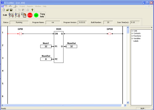
You have completed the ROR exercise.

  Previous PageNext Page