Previous PageNext Page

TIMERS

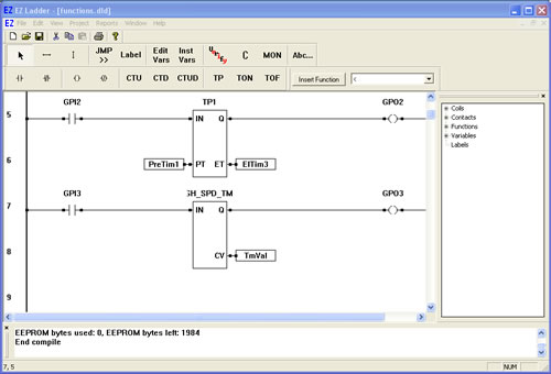
HIGH_SPD_TMR - High Speed Timer
The HIGH_SPD_TMR is a 100 microsecond resolution timer. When the IN detects a rising edge transition, the timer resets and begins timing from zero. When the IN detects a falling edge transition, the timer latches the current timer value. CV holds the current elapsed time when the timer is timing and the latched elapsed timer value when the timer stops timing. The output will be in 100 microsecond increments as an integer. Example: if the CV is 1000 then the actual time would be 100 milliseconds.
  1. We will now add the HIGH_SPD_TMR to our previously created ladder diagram.
  2. Place EZ LADDER® in the Edit mode (if in the Monitor mode).
  3. Using the Insert Function drop down menu on the tool bar, select HIGH_SPD_TMR..
  4. Place the cursor on Rung 7 near the center of the ladder diagram workspace and left-click to place the object. The Function Block properties dialog box will appear. Keep the name HIGH_SPD_TMR1 and leave the description blank (The name field allows you to set any name for the function while the description allows you to set a text description of what the function is used for). Click OK. The HIGH_SPD_TMR1 is now placed on rung 7.
  5. Select the DIRECT CONTACT button from the tool bar.
  6. Place the cursor on Rung 7 near the left power rail and left-click to place the contact. The Contact properties dialog box will appear. Using the drop down menu in the dialog box, selct GPI3 and click OK. This finishes the placement of the contact that is tied directly to hardware input GPI3 (also named GPI3).
  7. Select the DIRECT COIL button from the tool bar.
  8. Place the cursor on Rung 7 near the right power rail and left-click to place the coil. The Coil properties dialog box will appear. Using the drop down menu in the dialog box, selct GPO3 and click OK. This finishes the placement of the contact that is tied directly to hardware output GPO3 (also named GPO3).
  9. Select the HORIZONTAL LINK tool.
  10. Draw a link from the right side of the GPI3 contact to the IN of HIGH_SPD_TMR1.
  11. Draw a link from the Q output of HIGH_SPD_TMR1 to the left side of the GPO3 coil.
  12. We now need to insert variables to give the HIGH_SPD_TMR1 timer setpoints. Select the INST VARS button from the tool bar.
  13. Place the cursor on Rung 8 just right of the CV (current value) output on HIGH_SPD_TMR1. Left-click to insert the variable. The Variables dialog box will appear (the only tab available will be the INTEGER tab) since this is connecting to a the high speed timer function.
  14. Click the ADD button to add a new timer variable. The Add timer dialog box will appear. Type TmVal for the Name and set the type of variable to INTERNAL (leave other fields blank). Click OK. With this new variable still selected, click OK again. This sets the variable connected to the high speed timer's CV to this variable (which can be used to view the current value when running the program on the target).
  15. Save the ladder diagram from the File menu and selecting SAVE. It is a good idea to periodically save your ladder diagram when developing it.
  16. Compile the target using the COMPILE button from the tool bar. Ensure that the compile is successful and there are no errors. If there are errors they must be corrected. Your ladder diagram should look similar to this:


  17. We are now ready to run the program on the target. Switch to the Monitor mode by clicking the MON button from the tool bar.
  18. Connect to the target, by selecting the CONNECT button from the tool bar. A dialog box will appear stating the "builds" of the programs are different (because you have recompiled the program again). Click OK to continue.
  19. Download the ladder diagram to the target by selecting the DOWNLOAD button from the tool bar. If successful, the ladder diagram is now operating on the target. It should look similar to:


  20. Close the switch that is connected to Input 3 on the Development Board. GPI3 turns red indicating power flow and GPO3 turns red indicating power flow. The timer is now timing.
  21. Open the switch that is connected to Input 3 on the Development Board. GPI3 turns blue indicating no power flow and GPO3 turns blue indicating no power. The timer stops. The displayed value for variable TmVal is the amount of elapse time GPI3 was true. This number is a representation of the number of 100 microsecond time increments have elapsed.

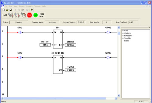
You have completed the HIGH_SPD_TMR exercise.

Note: The TON, TOF and TP timer circuits are still functional in addtion to the HIGH_SPD_TMR timer circuit you just created.

  Previous PageNext Page